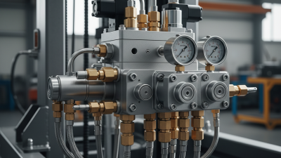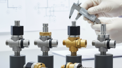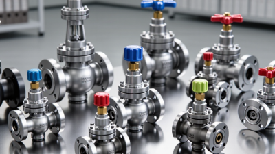
Directional Logic Element Valves are compact hydraulic components that control flow through cartridge-style elements and manifold passages. Their appeal is practical: several functions can fit inside a steel block, reducing external piping and potential leak points. In a machine circuit, a small pilot signal may shift a spool or poppet, redirecting oil to a cylinder or motor. The choice affects response, pressure loss, stability, and service access. Small details matter.
Industry data helps frame the subject, but it does not provide a simple ranking of valve designs. The National Fluid Power Association’s published shipment reports track broader fluid-power market activity; they do not identify one universally preferred logic-valve type. ISO 1219-1 provides standardized symbols for reading fluid-power diagrams, helping engineers compare circuit functions consistently. These sources offer context, not a substitute for checking operating pressure, flow, contamination tolerance, and installation space. There is no universal winner.
This guide examines common directional logic element types, including two-way and three-way elements, as well as pilot-operated configurations used in more complex circuits. It explains where each type fits, what trade-offs appear in real manifolds, and which specifications deserve close review. A valve may look right on paper yet respond slowly in a cold-start system. That is easy to overlook. Selection should follow the circuit’s actual duty, manufacturer data, and qualified engineering review—not a broad product label alone.
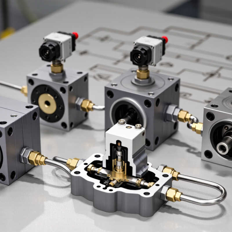
A shuttle valve performs a simple OR function: pressure at either inlet can create a signal at the outlet. Inside, a small ball or spool shifts toward the inactive side, allowing the pressurized inlet to connect through. The other inlet is blocked. One outlet. Two inputs.
In a pneumatic control circuit, for example, two separate push buttons can send air to one downstream actuator. Press either button, and the shuttle valve passes that signal onward. In hydraulic systems, it can select between pressure signals from different branches. The moving element responds to pressure, so the outlet receives the available signal without requiring a separate electrical control.
The diagram looks tidy. Real circuits can be less tidy. Contamination, worn sealing surfaces, or an unexpected pressure difference may affect switching and cause leakage or delayed response. Check the valve’s pressure range, flow capacity, and fluid compatibility against the actual circuit. A shuttle valve is useful for combining signals, but it does not automatically provide a safe way to isolate equipment. That distinction is easy to overlook.
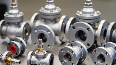
What Are the Top Types of Directional Logic Element Valves?
Dual-Pressure Valves: The AND Logic Element
A dual-pressure valve produces an output only when both input ports receive pressure. This makes it useful when a machine action should occur after two separate conditions are met. For example, two pneumatic signals can confirm that a guard is closed and a control is engaged. No signal from either input? No output. In many designs, output pressure is limited by the weaker input, so check the valve’s specifications and circuit diagram before selecting it.
Small details matter. A kinked tube, a leaking fitting, or pressure loss at one input can prevent the expected output. When troubleshooting, measure both inputs while the circuit is operating, rather than relying only on a static pressure reading. The logic is simple, but the installation is not always. It is worth reviewing whether both signals truly need to be present; otherwise, the valve may add complexity without improving control.
Tips: Label both input lines and keep them easy to trace. Test the valve with each input alone, then with both inputs together. If the output behaves inconsistently, check for contamination, leaks, and pressure differences before replacing components.
Check valves are simple directional logic elements: they allow flow forward and resist reverse flow without an external control signal. In a hydraulic line, a spring-loaded inline valve may help hold pressure, while a swing check valve suits larger, lower-velocity piping. Selection depends on more than pipe size. Cracking pressure, fluid viscosity, installation angle, and reverse-pressure rating all affect performance.
The market context is substantial. Grand View Research estimated the global industrial valves market at USD 78.4 billion in 2023 and projected a 4.3% compound annual growth rate from 2024 to 2030. This covers many valve types, not check valves alone, but it reflects how widely flow-control equipment is used. A check valve can still chatter or leak if it is oversized, contaminated, or exposed to pulsating flow. Small details matter. And sizing is not always straightforward.
Tips: Confirm the arrow on the valve body matches the intended flow direction. Check the manufacturer’s pressure and temperature ratings against actual operating conditions. If reverse flow would create a hazard, do not treat a check valve as a guaranteed shutoff; inspect and test the system regularly.
| Check Valve Type | How It Works | Reverse-Flow Control | Common Applications | Key Selection Considerations |
|---|---|---|---|---|
| Poppet Check Valve | Fluid pressure lifts a poppet from its seat to allow flow in the permitted direction. A spring or system pressure returns it to the seat. | The poppet seats to block reverse flow. Sealing performance depends on the seat design, materials, and operating conditions. | Hydraulic circuits, lubrication systems, and compact fluid-control assemblies. | Check cracking pressure, rated pressure and flow, leakage requirements, and compatibility with the fluid. |
| Ball Check Valve | A ball moves away from its seat when forward pressure is sufficient, opening a passage for fluid. | Reverse pressure pushes the ball onto the seat, restricting flow in the opposite direction. | Water and process-fluid lines, pumps, and systems handling fluids that may contain small particles, subject to the valve design. | Consider ball and seat materials, particle size, installation orientation, and the valve’s pressure-drop characteristics. |
| Swing Check Valve | A hinged disc swings open with forward flow and returns toward the seat when flow slows or reverses. | Reverse flow moves the disc toward the seat. Closure behavior can depend on flow conditions and installation. | Water distribution, drainage, and larger-diameter piping systems. | Allow for the required installation space and check the manufacturer’s guidance on orientation, closure, and water-hammer risk. |
| Lift Check Valve | Forward pressure raises a guided disc or piston from its seat; reduced or reversed flow allows it to close. | The disc or piston returns to the seat to resist reverse flow. | Pressurized piping and applications where a guided closing element is suitable. | Confirm permitted mounting orientation, flow capacity, pressure rating, and the specified cracking pressure. |
| Dual-Plate Check Valve | Two spring-assisted plates open under forward flow and move back toward the closed position as flow falls or reverses. | The plates close against the seat to limit reverse flow. Spring assistance can support faster closure than some non-spring designs. | Compact piping layouts, including water, HVAC, and industrial process systems when compatible with the service. | Check face-to-face dimensions, flow direction, pressure and temperature limits, and suitability for the fluid and pipe orientation. |
| Pilot-Operated Check Valve | A check element allows free flow in one direction; a pilot-pressure signal acts on a control piston or poppet to release the reverse-flow lock. | Blocks reverse flow until the required pilot pressure is applied, enabling controlled release when the circuit calls for it. | Hydraulic cylinders and circuits that need to hold a load or retain pressure until a pilot signal is provided. | Verify pilot ratio, pilot pressure, leakage limits, load-holding requirements, and safe circuit design. |
| Foot Valve | A check valve fitted at the submerged inlet of a suction line opens during pumping and closes when the pump stops. | Helps prevent the suction line from draining back; many designs include a strainer to limit debris entry. | Pump suction lines drawing from tanks, wells, or other liquid sources. | Choose a suitable strainer, ensure adequate submergence and inlet flow area, and account for added suction-side pressure loss. |
Note: A check valve permits flow in its intended direction and restricts flow in the opposite direction. Cracking pressure, leakage, flow capacity, and operating limits vary by design and must be confirmed from the valve specifications.
Pressure-control valves add sequence and threshold logic to directional circuits. A sequence valve keeps a secondary actuator still until inlet pressure reaches its set point. Then it opens, directing flow to the next operation. In a clamp-and-drill circuit, for example, the drill should not advance before the clamp develops adequate force. A pilot-operated valve can help reduce pressure-related chatter, but pilot-line routing matters.
Set the threshold from the real load, not a diagram alone. Cylinder friction, temperature, and return-line backpressure can shift the observed switching point. ISO 4413:2010 provides safety requirements for hydraulic systems; it does not prescribe one universal sequence pressure. That distinction matters. A setting that works on a cold test bench may behave differently after a long production run.
Clean fluid supports repeatable operation. ISO 4406:2021 classifies particle contamination by size; code 18/16/13 corresponds to roughly 1,300–2,500 particles per millilitre at 4 μm(c), 320–640 at 6 μm(c), and 40–80 at 14 μm(c). This is a reporting code, not a universal cleanliness target. Verify the machine maker’s requirement and measure pressure at the valve during cycling. One imperfect habit is to adjust the spring until the sequence “sounds right.” It can mask a sticking spool, so record the set pressure and retest under load.
Double-Pilot Valves: Pneumatic Memory Logic
A double-pilot directional valve can retain its last spool position after the pilot signal disappears. This bistable behavior is often called pneumatic memory. A short air pulse shifts the spool one way; a pulse at the opposite pilot shifts it back. The valve remembers. Unlike a spring-return valve, it does not automatically return to a fixed position when the signal ends.
This feature can simplify pneumatic control circuits. For example, one pilot signal may route air to extend a cylinder, while the opposite signal routes air for retraction. The control signal can be brief, which may reduce the need for a continuous pilot command. Still, the valve only remembers its spool state. It does not necessarily hold a cylinder safely in place under load. That distinction is easy to overlook.
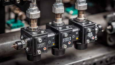
Designers should consider what happens after pressure loss or an unexpected pilot signal. The spool may remain in its last position, but the actuator’s behavior also depends on the circuit, load, and air supply. Check the valve’s operating-pressure range and port configuration against the application. Keep pilot lines clean and correctly connected; weak or conflicting signals can cause unreliable switching. In practice, memory logic is useful, but it deserves deliberate testing under real operating conditions.
A double-pilot directional valve retains its last spool position after a momentary pilot signal. The set pilot changes the output to 1; the reset pilot changes it back to 0. This logic sequence illustrates the memory behavior, not measured test data.