Leave Your Message
Choosing the right Pipe Counterbalance Valves in 2026 requires more than comparing catalog prices. These valves help control overrunning loads, stabilize hydraulic actuators, and reduce sudden movement in equipment such as cranes, lifts, excavators, and industrial platforms. A poorly matched valve may cause chatter, heat buildup, slow response, or unsafe load descent.
Real-world selection starts with measurable conditions. Engineers should check working pressure, flow rate, port size, pilot ratio, cracking pressure, and fluid compatibility. Installation direction also matters. On a vertical cylinder, the valve must hold the load without creating excessive back pressure. Temperature changes can alter oil viscosity and response time. Contamination remains a quiet problem. A clean filter often protects performance better than an expensive specification sheet.
This guide examines leading Pipe Counterbalance Valves available for modern hydraulic systems. It considers pressure stability, adjustment accuracy, response behavior, service access, manufacturer documentation, and long-term reliability. Field testing and technical data deserve equal attention. Marketing claims alone are not enough.
No ranking is perfect.
Different machines need different priorities. A compact mobile system may value low weight and simple adjustment. A high-cycle press may need stronger thermal control and precise pilot operation. Some products look similar but behave differently under unstable loads. That difference appears only during testing, maintenance, or an unexpected pressure spike. The recommendations ahead aim to support informed decisions, while acknowledging one limitation: real installation conditions can change the final result. Always confirm sizing and settings against verified manufacturer data and qualified hydraulic engineering practice.
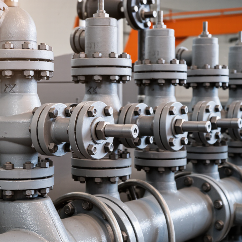
A pipe counterbalance valve controls overrunning loads in hydraulic circuits. It is commonly installed near a cylinder or motor port. Its main job is load holding, smooth lowering, and protection against uncontrolled movement. The valve stays closed until inlet pressure reaches its cracking setting. Pilot pressure then helps open it gradually. This action creates controlled back pressure behind the actuator. That small pressure prevents a suspended load from dropping suddenly.
ISO 4413:2010 requires hydraulic systems to address pressure control, hose failure, and unexpected actuator movement. These requirements explain why valve selection needs more than a catalog pressure rating. A 2024 MarketsandMarkets hydraulic equipment report forecasts roughly 5% compound annual growth through 2029. More equipment also means more demand for compact, reliable motion control. Still, market growth does not prove every valve suits every machine.
The top pipe counterbalance valves in 2026 should match working pressure, flow rate, load ratio, pilot ratio, and fluid cleanliness. A 3:1 pilot ratio may open smoothly, while a lower ratio can improve load stability. Check the valve near a loaded actuator, not only on a test bench. Listen for chatter during lowering. It often signals incorrect adjustment, trapped air, or excessive pilot pressure. Field experience matters here. A valve that looks efficient on paper may react poorly in cold oil or a long pipe run. My own caution is simple: never treat the preset spring as permanent. Load changes, temperature, and wear can shift real performance over time.
Comparison of common pipe-mounted counterbalance valve configurations used in hydraulic systems. Values are typical engineering ranges; the final selection must be verified against the manufacturer's current technical data and the complete circuit design.
| Valve Configuration | How It Works | Typical Pressure Range | Typical Flow Range | Common Pilot Ratio | Best-Fit Applications | Main Advantages | Key Selection Consideration |
|---|---|---|---|---|---|---|---|
| Direct-Acting Counterbalance Valve | A spring-loaded poppet or spool remains closed until pilot pressure and actuator pressure overcome the spring setting, controlling reverse flow from the actuator. | Up to approximately 350 bar (5,000 psi), depending on construction and size. | Approximately 5–120 L/min (1.3–32 gal/min). | Usually not pilot-ratio optimized; direct spring control is dominant. | Compact cylinders, small mobile equipment, light lifting mechanisms and simple load-holding circuits. | Simple design, fast response, strong load-holding capability and relatively low cost. | Can produce more pressure override and motion instability than a well-tuned pilot-operated design. |
| Pilot-Operated Counterbalance Valve | Load-induced pressure keeps the valve closed; pilot pressure from the opposite actuator port progressively opens the valve during controlled lowering. | Commonly 210–350 bar (3,000–5,000 psi). | Approximately 15–500 L/min (4–132 gal/min). | Common ratios include 3:1, 4.5:1 and 10:1. | Booms, winches, aerial platforms, telescopic handlers and high-load cylinders. | Better lowering control, reduced pressure override and improved energy efficiency compared with many direct-acting designs. | Incorrect pilot-ratio selection can cause chatter, uncontrolled lowering or excessive sensitivity to load changes. |
| Dual Counterbalance Valve | Two counterbalance elements are combined in one body to control both actuator directions, often with cross-piloting between the two work ports. | Typically 210–350 bar (3,000–5,000 psi). | Approximately 20–400 L/min (5–106 gal/min), depending on port size. | Commonly 3:1 to 10:1 for each side. | Hydraulic motors, reversible cylinders, rotating equipment and suspended loads requiring control in both directions. | Compact installation, synchronized bidirectional load control and fewer external components. | Both settings must be matched to the motor or cylinder, load inertia and operating direction. |
| Sandwich or Modular Counterbalance Valve | Installed between a directional control valve and a subplate or manifold; internal passages provide pilot and return-flow control without separate pipe runs. | Typically 250–315 bar (3,625–4,570 psi). | Approximately 10–250 L/min (2.6–66 gal/min). | Usually 3:1, 4.5:1 or 10:1. | Standardized hydraulic power units, machine tools and systems designed around modular valve stacks. | Clean installation, simplified maintenance and reduced external tubing. | Mounting pattern, port orientation, stack height and valve compatibility must be checked before selection. |
| Flange-Mounted Pipe Counterbalance Valve | Mounts directly to the actuator or motor port through a flange connection, minimizing the length of hose or pipe between the valve and load. | Commonly 250–420 bar (3,625–6,090 psi) for heavy-duty designs. | Approximately 40–1,000 L/min (11–264 gal/min). | Often 3:1 to 10:1, selected according to load and stability requirements. | Large hydraulic motors, winches, cranes, presses and high-flow lifting circuits. | Improves load security by reducing the amount of unprotected downstream piping. | Flange standard, bolt pattern, sealing method and installation space must match the actuator. |
| Counterbalance Valve with Anti-Cavitation Check | Combines load-holding control with an auxiliary make-up check valve that allows oil into the actuator when outlet flow exceeds available inlet flow. | Typically 210–350 bar (3,000–5,000 psi). | Approximately 15–500 L/min (4–132 gal/min). | Commonly 3:1 to 10:1. | High-inertia motors, overrunning loads, winches and circuits exposed to rapid deceleration. | Helps prevent cavitation, vibration and motor damage during overrunning or sudden stopping. | Make-up flow capacity, reservoir arrangement and return-line back pressure must be evaluated. |
| Counterbalance Valve with External Drain | Uses a dedicated drain connection to route spring-chamber or pilot-stage leakage directly to tank, preventing back pressure from affecting valve operation. | Typically 210–350 bar (3,000–5,000 psi). | Approximately 10–500 L/min (2.6–132 gal/min). | Commonly 3:1 to 10:1. | Systems with significant return-line pressure, hydraulic motors and circuits using multiple valves in series. | More predictable pressure control and reduced sensitivity to downstream back pressure. | The drain line should be correctly sized and routed to a low-pressure tank connection. |
| Electrically Controlled or Proportional Counterbalance Valve | An electrical solenoid or proportional stage changes the effective pilot or spring control, allowing remote adjustment of load-holding and lowering characteristics. | Commonly 210–350 bar (3,000–5,000 psi). | Approximately 10–300 L/min (2.6–79 gal/min). | Depends on the hydraulic pilot stage; often 3:1 to 10:1. | Automated machinery, variable-load handling equipment and systems requiring electronic motion control. | Remote control, adjustable response and integration with electronic machine control. | Requires electrical compatibility, fail-safe behavior, filtration and control-system validation. |