How to Choose Directional Logic Element Valves
Choosing Directional Logic Element Valves starts with the circuit, not the catalog page. These compact components control flow paths through pressure signals and internal logic, often inside manifolds where space is tight and service access is limited. A valve that fits the cavity may still respond poorly if its pressure range, flow capacity, or switching behavior conflicts with the system. Small details matter. A slow response can affect actuator timing; contamination can cause a spool or poppet to stick. Selection deserves careful thought.
Herbert E. Merritt’s hydraulic-control work offers a useful systems perspective. A practical selection principle, consistent with that approach, is: “Choose by circuit function and operating conditions, not by the valve label alone.” This is an editorial summary, not a verified verbatim quotation. In this guide, we will examine operating pressure, flow demand, logic function, fluid cleanliness, and installation constraints. We will also consider how to check manufacturer data and confirm performance under realistic conditions. For example, compare the stated flow rating with the pressure drop expected across the valve, rather than treating the maximum rating as a target. A sound choice should be explainable from the circuit diagram and supported by technical documentation. Even then, real installations can surprise us. That is worth remembering.
Understanding Directional Logic Element Valves and Their Functions
How to Choose Directional Logic Element Valves
Understanding Directional Logic Element Valves and Their Functions
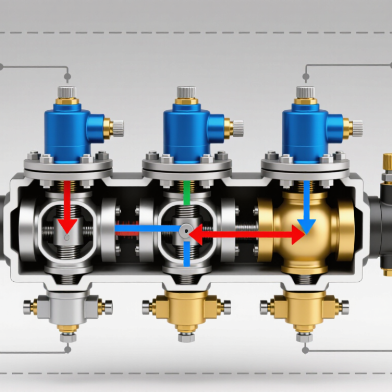
Directional logic element valves control flow paths inside a hydraulic manifold. A poppet or spool moves when pilot pressure overcomes spring force and hydraulic forces. This opens, closes, or connects ports according to the circuit design. The result can be a compact way to manage functions such as load holding, sequencing, and flow direction. Small details matter: a trapped pilot line or incorrect spring setting can change how a valve responds under load.
Choose the element by starting with the circuit’s required function, then check operating pressure, rated flow, leakage, and response time. Confirm that the cover, cavity, and pilot arrangement match the schematic. Do not select by port size alone. The U.S. Department of Energy’s 2006 Improving Pumping System Performance sourcebook reports that pumping systems can account for 25–50% of energy use in some industrial plant operations. That figure concerns whole pumping systems, not valves specifically, but it shows why avoidable pressure losses deserve attention. Still, catalog diagrams do not capture every real-world condition.
Tips: Check pilot pressure at the valve, not only at the pump. Test the circuit with the actual load, oil temperature, and expected flow. Keep records. A little extra review can prevent a confusing field fault.
Defining System Requirements and Operating Conditions
How to Choose Directional Logic Element Valves
Defining System Requirements and Operating Conditions
Start with the circuit’s actual job. Record required flow for every operating state, not just the pump’s rated output. Note peak pressure, return-line backpressure, and pressure spikes during switching. A valve that works at steady pressure may behave differently when a cylinder stops abruptly. I still see port size used as a shortcut for selection. It can mislead.
Fluid conditions matter just as much. Specify the fluid type, expected viscosity range, and minimum and maximum operating temperatures. ISO 4406 provides a particle-count coding system for hydraulic-fluid cleanliness; a target such as 18/16/13 gives maintenance teams a measurable reference. Check the element’s contamination sensitivity and required filtration against the circuit’s real conditions. Clean oil helps. So does a serviceable filter.
Define control details before choosing the cartridge and cover: pilot pressure, switching time, leakage tolerance, and whether the valve must hold a load after power loss. The U.S. Department of Energy’s Improving Pumping System Performance sourcebook reports that pumping systems can account for 25–50% of energy use in some industrial facilities. That makes pressure loss worth measuring, not guessing. Log fluid temperature and pressure during a full duty cycle; one test rarely captures every operating condition.
Selecting Valve Functions, Flow Paths, and Control Methods
How to Choose Directional Logic Element Valves
Selecting Valve Functions, Flow Paths, and Control Methods
Choose the valve function from the actuator’s required motion, not from a catalog label. A double-acting cylinder usually needs clear extension and retraction paths; a motor may need reversible flow and dependable stopping. Sketch the circuit and mark each port, load direction, and neutral condition. A tidy schematic can still hide a pressure spike.
Check flow capacity, operating pressure, leakage tolerance, and response time against real duty cycles. The U.S. Department of Energy’s Improving Pumping System Performance sourcebook reports that pumping systems use nearly 20% of global electricity demand, with some industrial facilities allocating 25–50% of energy to pumping. Those figures describe pumping systems broadly, not directional valves alone, but they show why avoidable pressure losses deserve attention. Match valve passages to required flow; undersized paths can create heat and slow movement. Small detail.
Then select the control method: manual control suits simple, hands-on adjustment; electrical actuation supports remote switching; pilot control can operate larger flows with a smaller command signal. Check voltage, signal behavior, contamination limits, and fail position. For example, a dusty machine may need more attention to spool protection than a clean test bench. I would still verify response under cold starts and changing loads; paper specifications rarely capture every installation quirk.
Checking Hydraulic Compatibility and Installation Constraints
Start with the hydraulic circuit, not the valve label. Compare system pressure and flow with the valve’s continuous and peak ratings; even brief pressure spikes matter. Check fluid type, viscosity during cold starts, and expected operating temperature against the specifications. Confirm that spool function and leakage behavior suit the actuator. A load-holding cylinder may need tighter control than a motor circuit. Small mismatch, big trouble. Slow movement often gets blamed on the pump, though a restrictive valve or undersized passage may be responsible.
Installation conditions can rule out an otherwise suitable valve. Measure the mounting face, port pattern, overall envelope, and space needed to remove coils or service fasteners. Leave room for hose bends; a line pressed against a frame can fatigue near its fitting. Check pressure drop at actual flow, not just nominal port size. For electrically actuated valves, verify connector orientation, voltage, and coil duty. Keep contamination control in view: clean, capped lines and suitable filtration help protect close-fitting components. Measure twice. Drawings can miss real obstacles, so inspect the assembly in place before ordering.
Evaluating Performance, Reliability, and Maintenance Needs
Choosing a directional logic element valve means checking how it performs in the actual circuit, not just its rated flow. Compare required flow and pressure with published operating limits, then assess pressure drop at the expected working point. An undersized valve can generate heat and slow an actuator. An oversized one may add cost without improving control.
Watch response time. If loads change quickly, check switching behavior under realistic pressure and fluid-temperature conditions. Reliability also depends on clean oil, stable seals, and resistance to repeated pressure cycles. Review test data for leakage and switching consistency, rather than relying on a single peak-performance figure. Installation details matter too: restricted passages or poor alignment can undermine an otherwise suitable valve. Small details count.
Maintenance needs should be considered before selection. Check whether inspection points are accessible and whether the element can be removed without disturbing nearby lines. Look for clear guidance on acceptable fluid cleanliness, seal replacement, and troubleshooting. A clean filter helps, but it does not excuse a difficult service layout. In practice, maintenance plans are sometimes based on ideal conditions; real systems may run hotter or collect more contamination than expected. Factor in those imperfections when setting inspection intervals.