Selecting a Bidirectional Relief Valve is not a catalog exercise. It is a pressure-management decision with consequences for equipment, operators, and production continuity.
Industry reports show why this decision deserves careful attention. Grand View Research has valued the global industrial valves market at more than USD 78 billion in recent estimates, with demand supported by energy, chemical processing, water, and manufacturing projects. Meanwhile, the International Energy Agency continues to identify industrial efficiency and process reliability as major investment priorities. These figures do not prove that one valve suits every installation. They do show the scale of the systems where valve performance matters.
A practical choice begins with the pressure envelope. Confirm the normal operating pressure, maximum allowable working pressure, temperature range, and possible pressure reversal. Check whether the valve must protect both sides independently. Small details matter. A blocked outlet, thermal expansion, or a rapidly closing actuator can create a dangerous pressure spike.
This guide presents ten selection tips based on engineering practice, manufacturer documentation, and recognized standards, including API 520, API 521, and ASME Section VIII. These standards help engineers evaluate sizing, discharge capacity, materials, and inspection requirements. Still, standards are not substitutes for site knowledge. Fluid viscosity, corrosion, pulsation, installation orientation, and maintenance access can change the result.
Some choices look efficient on paper. They may fail during testing.
Reliable selection requires verified flow data, certified test results, traceable materials, and clear service records. It also requires honest review. Engineers sometimes underestimate reverse-pressure scenarios because normal operation appears stable. That assumption deserves challenge. A correctly specified Bidirectional Relief Valve should respond predictably in both directions, protect connected equipment, and remain serviceable throughout its expected operating life.
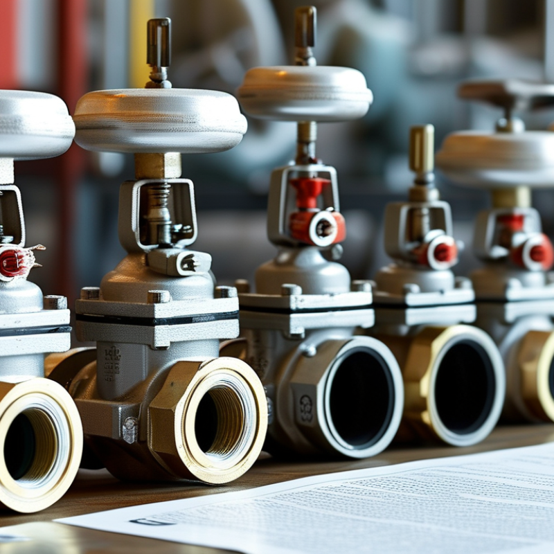
A bidirectional relief valve protects equipment when pressure rises from either flow direction. Its main parts usually include a spring, sensing element, seat, and discharge path. When pressure reaches the set point, the valve opens and releases excess pressure. As pressure falls, the spring pushes the seat closed again. This is the basic operating principle.
The valve must respond correctly on both sides. Piping pressure, temperature, fluid density, and backpressure can change its performance. In field inspections, I check the flow arrows, mounting position, and discharge route before reviewing the data sheet. A small installation mistake may cause unstable opening or slow reseating. The ideal setting is not always obvious.
10 Tips for Choosing a Bidirectional Relief Valve
Define Pressure, Flow, Temperature, and Media Requirements
Selecting a bidirectional relief valve starts with defining pressure in both flow directions. Record normal operating pressure, maximum allowable pressure, set pressure, and expected backpressure. A pressure gauge reading alone is not enough. System pressure can change quickly during startup, shutdown, or blocked-line conditions. Numbers alone are insufficient.
Flow data should include the required relief rate, fluid phase, density, viscosity, and allowable pressure drop. Check both directions, even when one direction seems less demanding. A valve sized for liquid may respond poorly with flashing fluid or entrained gas. Calculate realistic worst-case conditions, not convenient averages. That mistake is costly.
Temperature affects sealing, spring performance, body strength, and material compatibility. Record minimum, normal, and maximum temperatures, including short thermal spikes. Describe the media precisely: clean water, abrasive slurry, corrosive chemical, gas mixture, or contaminated process fluid. Small particles can prevent proper reseating. Confirm compatibility with every wetted component, not only the main body. In field reviews, incomplete media descriptions often create avoidable failures. I have seen specifications omit cleaning chemicals and winter exposure. Those details matter. Keep the test record. Also verify whether pressure relief is needed during thermal expansion, pump isolation, or reverse flow. A careful specification may still need revision after site measurements.
| No. | Selection Dimension | Requirement to Define | Practical Selection Guidance | Example Design Input | Verification Check |
|---|---|---|---|---|---|
| 1 | Define the Pressure Direction | Confirm whether pressure relief is required in both flow directions and identify the protected pressure zones. | Use a valve specifically designed for bidirectional operation. A standard one-way relief valve may not provide the same set pressure or flow capacity in reverse flow. | Relief required from Vessel A to Vessel B and from Vessel B to Vessel A. | Check the manufacturer’s bidirectional performance data and flow-direction markings. |
| 2 | Set Pressure | Specify the intended opening pressure for each direction, together with the normal operating pressure. | Set pressure should be above the maximum normal operating pressure but below the allowable working pressure of the protected equipment. Account for tolerance and pressure buildup. | Normal pressure: 6 bar(g); target opening pressure: 8 bar(g); equipment allowable pressure: 10 bar(g). | Confirm set-pressure tolerance, cold differential test pressure, and allowable accumulation in the applicable design code. |
| 3 | Required Relief Flow | Calculate the maximum credible overpressure flow rate for each direction. | Consider pump shutoff flow, blocked discharge, thermal expansion, gas generation, control failure, and other credible scenarios. Size for the governing case rather than normal flow. | Required capacity: 420 L/min liquid in Direction A and 300 L/min liquid in Direction B. | Compare calculated demand with certified capacity at the actual inlet pressure, outlet pressure, and fluid properties. |
| 4 | Flow Coefficient and Pressure Drop | Define acceptable pressure loss during normal operation and the minimum flow coefficient required during relief. | Select sufficient effective flow area or flow coefficient. Excessive inlet pressure loss can cause unstable operation or reduce available relief capacity. | Maximum normal pressure drop: 0.2 bar; required liquid flow coefficient calculated from the system model. | Review certified capacity curves for both directions and verify inlet piping pressure loss. |
| 5 | Fluid or Media | Identify the fluid phase, chemical composition, concentration, density, viscosity, toxicity, flammability, and solids content. | Liquid, gas, vapor, and two-phase flow require different sizing methods. Corrosive, toxic, viscous, or particle-containing media may require special trim or sealing arrangements. | Water-glycol liquid, 40% concentration, density approximately 1,050 kg/m³, viscosity dependent on temperature. | Verify compatibility using concentration-specific chemical resistance data, not only the base-fluid name. |
| 6 | Temperature Range | Specify minimum, normal, maximum, start-up, shutdown, and potential transient temperatures. | Temperature affects material strength, seal performance, fluid viscosity, vapor pressure, and set-pressure behavior. Include ambient temperature where relevant. | Process temperature: 5–80°C; ambient range: −20–45°C. | Confirm the valve, spring, elastomers, and body materials are rated across the complete temperature range. |
| 7 | Materials and Corrosion Resistance | Define wetted-part materials, spring material, seat material, body material, and surface treatment requirements. | Select materials based on the actual medium, temperature, pressure, corrosion mechanism, and service life. Avoid relying on general material labels without compatibility confirmation. | Wetted parts require resistance to aqueous glycol, oxygen exposure, and repeated pressure cycling. | Review corrosion, erosion, galvanic compatibility, and seal-swelling data for the complete material combination. |
| 8 | Reseating and Leakage Performance | Specify reseating pressure, blowdown or hysteresis, allowable leakage, and the required tightness class. | A valve that opens too frequently can wear prematurely. Excessive leakage may contaminate the system, reduce efficiency, or create a safety hazard. | Target reseating pressure: at least 90% of set pressure; leakage limited to the specified test criterion. | Request documented seat-leakage and functional test results at the specified pressure and temperature. |
| 9 | Connections and Installation | Define connection size, connection type, pressure class, installation orientation, access, drainage, and discharge routing. | The connection must match the piping system and withstand reaction forces. Keep inlet passages short and unobstructed; route discharged media safely. | Inlet and outlet: DN25 flanged connections; horizontal installation; discharge routed to a closed collection line. | Check dimensional drawings, installation instructions, support requirements, and allowable backpressure. |
| 10 | Testing, Standards, and Maintenance | Define required design code, inspection documents, pressure tests, set-pressure tests, service interval, and replacement parts. | Select a valve that can be tested and maintained within the site’s quality system. The applicable standard depends on equipment type, jurisdiction, and service. | Required records: material certificates, pressure test report, set-pressure report, dimensional drawing, and maintenance instructions. | Confirm regulatory acceptance, traceability, calibration status, inspection frequency, and availability of service kits. |
Choosing a bidirectional relief valve starts with pressure behavior, not catalog size. Confirm the set pressure, operating pressure, vacuum conditions, and allowable backpressure on both flow paths. API 520 Part I requires capacity calculations based on credible overpressure scenarios. A valve that looks adequate at normal pressure may fail during blocked discharge or thermal expansion. Check the certified flow coefficient, blowdown, response time, and reverse-pressure stability. Small details matter.
Material selection should follow the fluid, temperature, and contamination profile. Stainless steel may resist corrosion, but chloride exposure can still cause stress cracking. For sour service, review NACE MR0175 or ISO 15156 requirements. Match seals to temperature and chemical compatibility; elastomers often become the weakest component. ISO 4126-1 provides a recognized framework for safety-valve performance and testing. Ask for material certificates, pressure-test records, and calibration evidence. Paperwork is not decoration.
Field reports deserve attention. The U.S. Chemical Safety Board’s investigation reports repeatedly connect inadequate relief-system design, isolation, and maintenance with major loss-of-containment events. IOGP’s Safety Performance Indicators also track process-safety events as a core risk measure. Use those lessons practically: inspect the valve after installation, verify the discharge route, and test both directions where applicable. I still distrust a perfect datasheet without operating history. Consider erosion, vibration, and dirt at the inlet. Then reassess the selection after real service data arrives.
Evaluate valve design, materials, pressure ratings, and service conditions before selecting a bidirectional relief valve. The chart below provides a pressure-class reference at 38°C (100°F) for a carbon-steel material group in accordance with ASME B16.34. These values are reference pressure ratings, not relief-valve set pressures.
Selection checklist: Confirm bidirectional flow performance, set pressure, reseating behavior, pressure class, temperature range, body and trim materials, seal compatibility, leakage requirements, connection standard, and inspection or testing requirements. Always verify the final pressure-temperature rating with the applicable valve standard and manufacturer documentation.
Reference pressure ratings at 38°C: Class 150: 19.6 bar, Class 300: 51.0 bar, Class 600: 102.0 bar, Class 900: 153.1 bar, Class 1500: 255.5 bar, Class 2500: 425.4 bar. Actual allowable pressure depends on the material group, temperature, design standard, and valve construction.
Compare operating pressure, set pressure, flow capacity, and reverse-flow behavior before reviewing price. The valve must protect both pressure directions. Check the rated temperature range, media compatibility, and material strength.
API 520 and API 521 provide recognized guidance for sizing and pressure-relief applications. ISO 4126 also defines safety requirements for industrial relief devices.
Standards matter.
Installation details can decide performance. Confirm the inlet and outlet sizes. Check whether the valve tolerates vibration, pulsation, and changing flow direction. Keep discharge piping short and properly supported. Avoid unnecessary elbows near the valve.
ASME Boiler and Pressure Vessel Code Section VIII requires suitable overpressure protection for covered pressure equipment.
A compliant valve can still fail in a poorly designed system.
Maintenance needs evidence, not assumptions. Schedule inspection according to service severity, cycling, and corrosion risk. Test the set pressure and resealing performance. Record every adjustment.
The U.S. Department of Energy reports that compressed-air leaks may waste 20–30% of compressor output, showing how small losses become expensive.
A relief valve leak can create similar hidden waste. I have seen specifications focus heavily on capacity while ignoring access for testing. That is an avoidable mistake.
Choose visible tags, replaceable seals, and clear service instructions. Some calculations look precise, yet field conditions remain uncertain.
Recheck them after commissioning.
A bidirectional relief valve must protect equipment in both flow directions. Selection should begin with the real operating conditions, not a catalog pressure alone. Review fluid type, temperature range, flow rate, pressure fluctuations, and available installation space. A valve that suits clean water may respond poorly to a viscous or contaminated medium.
Tip 1: Test the valve in both directions. Confirm opening pressure, reseating pressure, response time, and leakage at each port. Use calibrated gauges and record results. Repeat tests at expected operating temperatures when practical. Small differences can matter.
Tip 2: Check safety margins. Compare the valve setting with normal pressure, pump surges, and the equipment’s maximum allowable working pressure. Do not assume the factory setting matches your system.
Tip 3: Review installation details, including pipe orientation, isolation devices, drain paths, and access for inspection.
Application review often exposes overlooked problems. Examine pressure logs from the actual system, especially during startup and shutdown. Confirm that the discharge route can handle the released fluid safely. Verify material compatibility with the fluid and surrounding environment. Experienced technicians also inspect vibration, pipe strain, and debris risks. These factors can affect valve stability. A clean test result is useful, but it is not permanent proof. Conditions change, and maintenance records may be incomplete. Build in periodic retesting, clear acceptance criteria, and documented corrective actions before service begins.