How to Choose Stacked Counterbalance Valves in 2026
Choosing Stacked Counterbalance Valves in 2026 is not just a matter of matching port sizes. These assemblies help control overrunning loads, limit drift, and manage motion when a hydraulic actuator moves under gravity or external force. The National Fluid Power Association (NFPA) publishes industry trend and shipment reports that track changes in fluid-power demand. Those reports provide useful market context, but they cannot tell engineers which valve will hold a specific load safely. That decision starts with the circuit.
Small details matter. A valve that looks suitable on a drawing may behave differently once oil warms, a cylinder moves, or a load changes direction. Compare rated pressure and flow with expected peaks, not just normal operating values. Check pilot ratio, load-induced pressure, leakage expectations, port configuration, and the effects of stacking sections. ISO 4413 sets general safety requirements for hydraulic fluid-power systems; it is a useful reference, not a substitute for application-specific verification. Test the complete assembly under realistic conditions. A neat stack can still be a poor choice. And specifications can leave questions unanswered.
This guide explains how to evaluate Stacked Counterbalance Valves for equipment planned or upgraded in 2026. It focuses on practical selection, compatibility, and evidence to request from suppliers, including performance curves and installation limits. Some trade-offs remain. A compact manifold may simplify plumbing, yet make servicing less convenient. Treat that as a design question, not an afterthought.
What Stacked Counterbalance Valves Are and How They Function
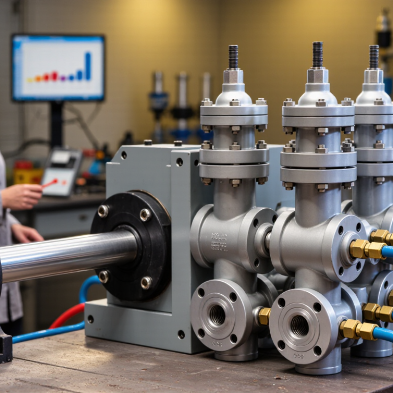
Stacked counterbalance valves combine load-control sections in a shared manifold, helping compact hydraulic circuits hold and lower suspended loads. Each section creates controlled resistance at the actuator’s outlet. Pilot pressure from the opposite line helps open the valve when lowering is commanded. This can reduce uncontrolled descent if a hose fails, but it does not replace sound circuit design or maintenance. The actual response depends on load, pressure, oil temperature, and valve settings.
The U.S. Department of Energy’s Improving Pumping System Performance sourcebook reports that pumping systems use nearly 20% of global electricity and can account for 25–50% of energy use in some industrial facilities. Those figures cover pumping systems broadly, not counterbalance valves specifically. Still, they show why excess pressure loss deserves attention. In practice, a valve set too high may create heat; set too low, it may allow load drift or unstable motion. I would verify settings under the real load, not rely on a diagram alone. ISO 4413 also provides general safety requirements for hydraulic systems.
Tips: Check the load-induced pressure, pilot ratio, return-line backpressure, and relief settings together. Test lowering with the actual cylinder or motor and load. Small changes matter. Record the final setting and recheck it after commissioning; field conditions can expose assumptions that looked reasonable on paper.
How to Assess Load, Pressure, and Flow Requirements
Choosing stacked counterbalance valves starts with the load, not the valve’s headline pressure rating.
Estimate the maximum load-induced pressure at the cylinder or motor, including linkage geometry and changing load position. Then set the valve’s holding pressure above that value, while checking the component’s pressure limits and the manufacturer’s recommended setting margin. Small geometry changes can matter. Recheck the calculation.
Next, size for actual flow in both directions.
Compare expected actuator flow with the valve’s rated flow, and account for pressure drop across every stacked section. A narrow passage can create heat, slow movement, or unwanted instability. Check peak flow during rapid motion, not only the system’s average. The U.S. Department of Energy’s Improving Pumping System Performance sourcebook estimates that pumping systems consume nearly 20% of global electricity. That broad figure is not a counterbalance-valve sizing rule, but it shows why avoidable hydraulic losses deserve attention.
Finally, verify the circuit under realistic conditions:
load variation, oil temperature, and possible pressure spikes. ISO 4413:2010 provides general safety requirements for hydraulic fluid-power systems, including pressure-related design considerations. Use it alongside the valve’s technical documentation, rather than treating a single setting as universal. I would still review the assumptions after commissioning; real machinery can reveal load changes that drawings missed. Good selection is measured, then checked again.
How to Select Valve Configuration and Performance Ratings
How to Choose Stacked Counterbalance Valves in 2026
How to Select Valve Configuration and Performance Ratings
Choose the valve arrangement around the actuator and load. A single valve may suit a one-direction suspended load; a dual arrangement can control overrunning loads in both directions. In a stacked assembly, confirm port alignment, section flow capacity, and whether neighboring functions create pressure interaction. Set the pressure rating above the highest expected operating pressure, including credible transient spikes. The valve’s flow rating matters too: a narrow passage can cause heat and slow actuator movement.
Select the pilot ratio and setting for stable control, not merely easy opening. A high ratio reduces required pilot pressure but can make a load more sensitive to pressure changes. Start with the load-induced pressure, then validate the setting against the valve maker’s curves and the actual cylinder geometry. ISO 4413:2010 provides hydraulic-system design and safety guidance. For contamination control, ISO 4406:2021 classifies particle counts at sizes above 4, 6, and 14 μm(c); cleanliness affects small valve clearances. Real systems are imperfect. Test under the heaviest load and at operating temperature.
Tips: Record peak pressure and flow at the actuator. Check for drift, chatter, and heat after cycling. A tidy schematic can still miss a stubborn field condition.
How to Check Compatibility with the Hydraulic System
Check compatibility at operating conditions, not just on a catalog page. Record maximum and normal pressure, flow, fluid type, temperature, and return-line backpressure. Then compare them with the valve’s rated limits and the hydraulic schematic. A valve that fits the manifold may still behave poorly if its pilot ratio conflicts with the cylinder load or circuit pressure.
Mind the details. Confirm port size, cavity or mounting pattern, adjustment range, and whether the stack changes flow paths. Check that the selected seal material suits the actual fluid and temperature; “hydraulic oil” is not specific enough. Fluid cleanliness matters too. ISO 4406:2021 reports particle contamination using three code numbers. For example, code 18/16/13 represents approximately 1,300–2,500 particles per millilitre at 4 μm(c), 320–640 at 6 μm(c), and 40–80 at 14 μm(c). Treat this as a cleanliness description, not a universal target; follow the valve and system specifications. Before installation, compare the stack drawing with the manifold ports and check the circuit’s measured backpressure. Small mismatches can cause heat or unstable load holding. Field notes are imperfect, so verify pressure readings under load rather than trusting an old service sheet.
How to Choose Stacked Counterbalance Valves in 2026: Check Hydraulic System Compatibility
Illustrative pressure check for a hydraulic circuit. Confirm actual operating conditions and component ratings against the system design and valve datasheet.
How to read the chart: The example circuit reaches 27 MPa during a transient, below the selected valve’s assumed 31.5 MPa maximum working-pressure rating. This comparison alone does not confirm compatibility.
Also verify: required flow capacity, pilot ratio and pilot pressure, fluid type and temperature range, port and mounting configuration, and pressure spikes. Use the maximum system conditions—not just normal operating pressure—when checking ratings.
How to Install and Verify Valve Operation Safely
Before installing a stacked counterbalance valve, secure the machine and lower or mechanically support the load. Isolate the power source, relieve hydraulic pressure, and verify zero pressure with a suitable gauge. Do not loosen a fitting to check for trapped pressure. Clean the mounting face and inspect the seals; grit or a pinched seal can cause leakage. Check the circuit diagram, port markings, stacking order, and specified fastener torque. Small details matter.
Mount the valve in its specified orientation and tighten fasteners evenly to the documented torque. Confirm that hoses and fittings are rated for the system pressure and cannot rub against moving parts. Keep the work area clean. A tidy setup helps, but it does not prove the circuit is safe. Have a qualified technician review the assembly before power is restored, especially if the stack or load path has changed.
Restore power gradually, with people clear of the suspended load and the test area. Use a controlled test procedure and suitable pressure instruments to check for leaks, stable load holding, and smooth lowering. Compare readings with the valve and machine specifications; do not adjust settings by guesswork. Stop if the load creeps, the valve chatters, or pressure behaves unexpectedly. Record the setup and results. Real systems can surprise you, so treat a successful first test as evidence, not a guarantee.